Overview
MikroTik RouterOS is designed to be easy to operate in various
aspects of network configuration. Therefore creating limitation for
individual IP or natting internal clients to a public address or Hotspot
configuration can be done without the knowledge about how the packets
are processed in the router - you just go to corresponding menu and
create necessary configuration.
However more complicated tasks, such as traffic prioritization,
routing policies, where it is necessary to utilize more than one
RouterOS facility, requires knowledge: How these facilities work
together? What happens when and why?
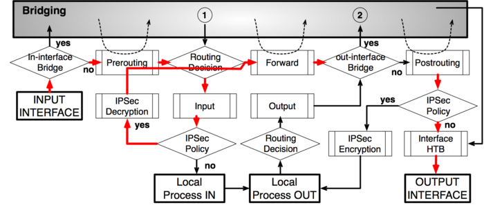
To address these questions we created a packet flow diagram.
Diagram
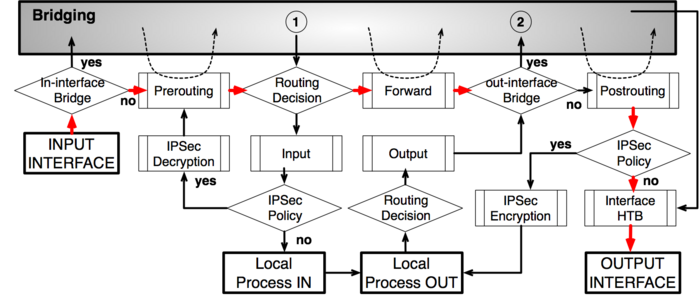
As it was impossible to get everything in one diagram,
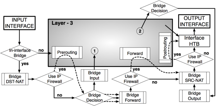
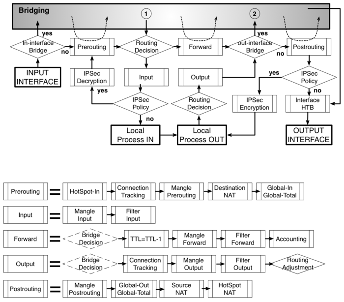
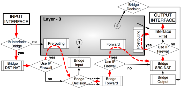
Packet flow diagram for Mikrotik RouterOS v3.x was created in 2 parts:
- Bridging or Layer-2 (MAC) where Routing part is simplified to one "Layer-3" box
- Routing or Layer-3 (IP) where Bridging part is simplified to one "Bridging" box
The packet flow diagram is also available as a PDF.
Analysis
Basic Concepts

- starting point in packets way through the router facilities. It does
not matter what interface (physical or virtual) packet is received it
will start its way from here.

- last point in packets way through the router facilities. Just before the packet is actually sent out.

- last point in packets way
to router itself, after this packet is discarded

- starting point for packets generated by router itself
Configurable Facilities
Each and every facilities in this section corresponds with one
particular menu in RouterOS. Users are able to access those menu and
configure these facilities directly
-
/ip firewall connection tracking

-
/ip firewall filter
-
/ip firewall nat

-
/ip firewall mangle


-
/queue simple and
/queue tree

-
/ip ipsec policy

-
/ip accounting

-
/interface bridge settings - available only for traffic that go
through the bridge. For all other traffic default value is
Yes
-
/interface bridge filter
-
/interface bridge nat
Automated processes and decisions

- check if the
actual input interface is a port for bridge OR checks if
input interface is bridge
- allow to capture traffic witch otherwise would be discarded by
connection tracking - this way our Hotspot feature are able to provide
connectivity even if networks settings are in complete mess
- bridge goes through the MAC address table in order to find a match to
destination MAC address of packet. When match is found - packet will be
send out via corresponding bridge port. In case of no match - multiple
copies of packet will be created and packet will be sent out via all
bridge ports
- this is a workaround, allows to use "out-bridge-port" before actual bridge decision.
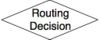
- router goes through the route n order to find a match to destination
IP address of packet. When match is found - packet will be send out via
corresponding port or to the router itself . In case of no match -
packet will be discarded.
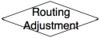
- this is a workaround that allows to set-up policy routing in mangle chain output
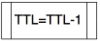
- indicates exact place where Time To Live (TTL) of the routed packet is reduced by 1. If it become 0 packet will be discarded
- self explainatory
- check if the
actual output interface is a port for bridge OR checks if
output interface is bridge
- undo all that was done by hotspot-in for the packets that is going back to client.
Examples
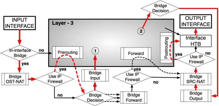
Bridging with use-ip-firewall=yes
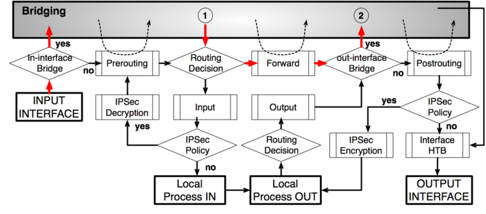
Routing - from Ethernet to Ethernet interface
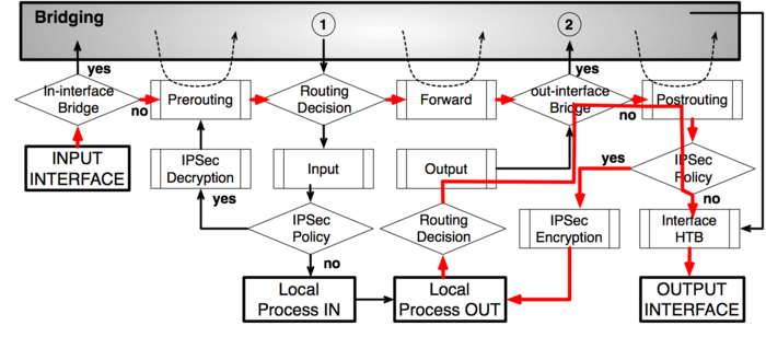
Routing from one Bridge interface to different Bridge interface
IPsec encryption
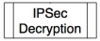
IPsec decryption
Tidak ada komentar:
Posting Komentar